A rule for two signals at once
Notes 22 and 25 showed that the cat circuit model does not add two superimposed gratings: the stronger one dominates. This note turns that into a decision rule for a controller that receives two signals at once, and tests it. Two signals are shown as two gratings at right angles; one number read from the circuit's response says which of three actions follows: A, B or hold. Every number of the rule was fixed on the pilot's one network instance and declared; the rule was then applied unchanged to the six instances of the confirmatory test. Declared outcome: PASS, the intended action in 336 of 336 test steps. A relay that adds the single responses would have erred in 5 of 24 cases. The test reuses held runs whose summary results were known and whose per-step readouts were already published, which is weaker than a fresh run; the rule also works on the pilot with the cortex's own connections removed, and no market signal or action is involved. Simulation only.
Note 20 found the cat circuit model to be a faithful relay when it is shown one input at a time. Notes 22 and 25 found that it is not a relay when it is shown two: of two superimposed gratings, the stronger one dominates and the weaker is suppressed. Note 22 added that a controller fed two signals at once "would need its own declared encoder".
This note declares that encoder and a decision rule on top of it, and tests the rule on network instances it was not designed on. The declared outcome is PASS: the intended action in 336 of 336 test steps, over six instances.
It is an engineering rule tested on recorded model runs. No market signal entered and no action was taken.
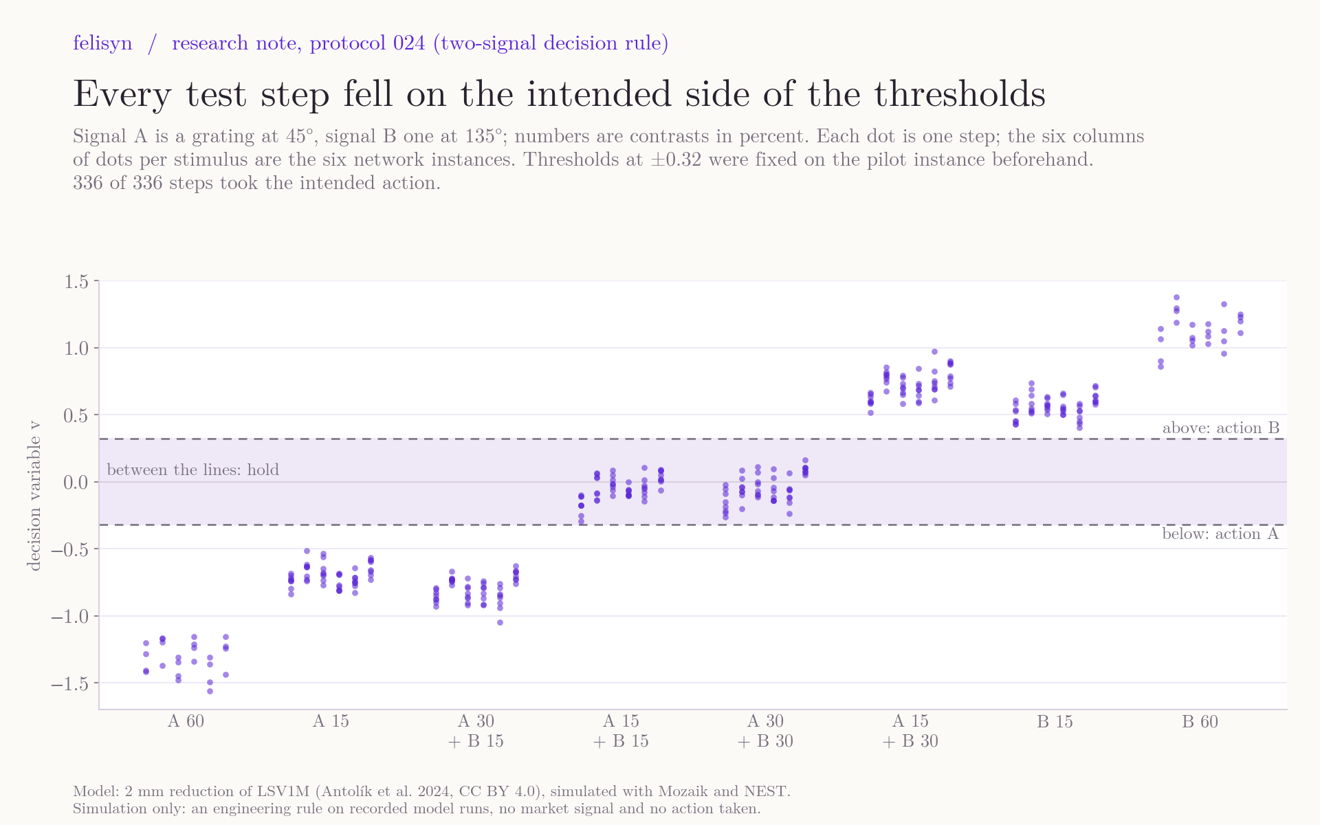
The rule
The rule has three parts, each an engineering choice and declared as one.
- Encoder. Two signals, A and B, are shown together for one step of 210 ms: A as a grating at 45°, B as a grating at 135°. The strength of a signal is the contrast of its grating, up to 30 %.
- Readout. The circuit's response is read with the frozen readout of note 18, unchanged: a weighted sum of the spike counts of all layer 4 excitatory cells, 40 to 300 ms after onset. On top of it, the rule forms one number, v. It subtracts the response to a grey screen, takes the part that lies along the axis from A to B, and divides by the size of the response to one signal alone at 30 %. A single signal at 30 % gives a v of roughly −1 for A and +1 for B (−0.98 to −1.20 and +0.80 to +1.02 in the six instances).
- Action. Action B if v is above 0.32, action A if it is below −0.32, hold in between.
Each network instance is calibrated on its own grey-screen steps and its own single gratings at 30 %. Those 24 steps are not scored.
Where 0.32 comes from. On the pilot's network instance, the largest |v| among steps with two equal signals was 0.22, and the smallest among steps with one weak signal alone was 0.42. The threshold is the midpoint. Nothing else was tuned.
The test
The six network instances of protocol 023 revision 2 each saw the same stimulus set, in their own order. It contains every combination of the strengths 0, 15 and 30 % for the two signals, and each signal alone at 60 %. For each stimulus the intended action is the obvious one:
- two equal signals: hold;
- two unequal signals: the action of the stronger;
- one signal alone: its action.
That gives 56 scored steps per instance. The grey-screen steps and the single gratings at 30 % calibrate the instance and are not scored. The declared outcome is PASS if every instance takes the intended action in at least 51 of its 56 steps and the six together in at least 320 of 336.
The rule, its threshold, the test steps and the pass marks were frozen and declared at 14:05:41 UTC on 13 November, with one independent review before. The tool then ran twice on the six exports, and the two result files are byte-identical.
The result
PASS: 56 of 56 on every instance, 336 of 336 in all.
| Stimulus (contrast in %) | Intended | Steps as intended | Mean v per instance |
|---|---|---|---|
| A 15 + B 15 | hold | 48 of 48 | −0.18 to +0.03 |
| A 30 + B 30 | hold | 48 of 48 | −0.15 to +0.09 |
| A 30 + B 15 | A | 48 of 48 | −0.87 to −0.70 |
| A 15 + B 30 | B | 48 of 48 | +0.60 to +0.82 |
| A alone, 15 | A | 48 of 48 | −0.76 to −0.64 |
| B alone, 15 | B | 48 of 48 | +0.50 to +0.64 |
| A alone, 60 | A | 24 of 24 | −1.43 to −1.23 |
| B alone, 60 | B | 24 of 24 | +0.99 to +1.28 |
The margins are real but not wide. Among steps meant to hold, the largest |v| was 0.294, against a threshold of 0.32; among steps meant to act, the smallest was 0.404. One step lay 0.026 from a threshold. A perfect score here does not promise one on the next instance.
The response scale differed little between instances (4,837 to 5,533, against 5,586 on the pilot), so the calibration step did little work.
What a relay would have done
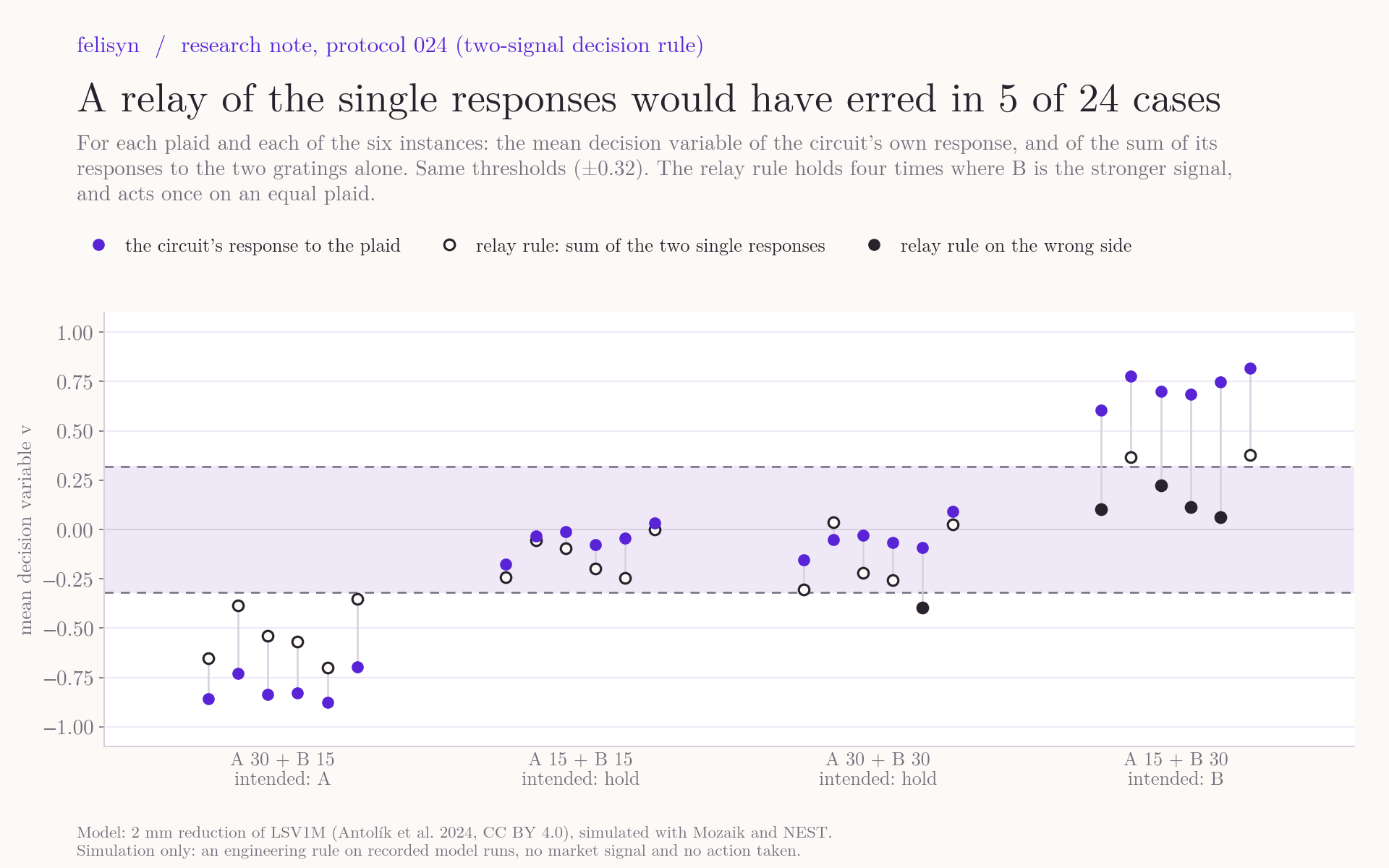
If the circuit simply added its responses to the two gratings, the same thresholds would give the intended action in 19 of the 24 combinations of plaid and instance. With A at 15 % and B at 30 %, the summed single responses stay inside the hold band in four of the six instances (+0.06 to +0.22), because a weak signal alone already evokes most of the response of a strong one (A alone at 15 % gives −0.64 to −0.76, B alone at 30 % gives +0.80 to +1.02), so their sum is small. The circuit's actual response to that plaid is +0.60 to +0.82 in every instance: the stronger signal wins by more than the sum predicts. On one instance the relay rule would also have acted on two equal signals at 30 %.
This is the suppression and dominance of notes 22 and 25, seen where a controller would use it. It is the same data and the same effect, not new evidence for it.
A third orientation
The stimulus set also holds a few steps with a grating at 90°, halfway between A and B. They were described, not scored, because the rule was not designed for them. A grating at 90° alone gives hold in all 48 steps. More telling: signal B at 15 % together with a 90° grating at 30 % gives hold in all 24 steps, although B alone at 15 % gives action B every time. A stronger input at another orientation masks a weak signal. A controller built on this rule must keep stray inputs away from the two signal orientations, or expect to hold when one is present.
What this does and does not show
- It shows a rule that works on this model, out of the instance it was fitted on. Threshold from one instance, intended action in every scored step of six others.
- The six instances were held data, and partly known. Their runs existed, their three summary measures were published in note 25 and already pointed this way, and protocol 023's analysis had published each instance's per-step readout in its results file, from which this outcome could have been computed. The declaration states that no per-step readout of the six was read, printed or used for the rule before it. The first draft of the spec wrongly said those readouts had never been computed; the reviewer caught that before the declaration. This is held data analysed again, not a fresh run, and weaker than one. The held-out status rests on the corrected statement, and the tool checks its own readout against the published one for all 576 steps.
- It does not show that the cortex's own connections make the decision. On the pilot's instance the rule also gives 56 of 56 with every connection inside the cortex set to zero. The rule reads the whole model, input stage and cortex together, as notes 22 and 25 did. No runs without those connections exist for the six instances.
- It is narrow. Three strengths per signal, one pair of orientations, one timing, one orientation map shared by all instances, one step per decision, calibration from the same run.
- It involves no market and no action. What signals A and B would stand for, and what actions follow, is not part of this protocol.
- It is simulation only, and no claim about cat visual cortex.
Next
- Signals that are not on the grid. The test used three strengths. A controller's signals vary continuously, so the step we intend next is a decision map over a finer grid of strengths on fresh runs, with the threshold from this note unchanged.
- Decisions over time. Each decision here used one step. Whether a short run of steps makes the close calls safer is a separate declared question.
Status on 13 November: neither has been declared.
Evidence and sources
- Decisions 024: the package, with:
- the declared results, computed twice (second file, byte-identical);
- the declared spec, the tool, its tests and the frozen manifest;
- the design run on the pilot, intact and lesion;
- the figures with their data and scripts, and the package manifest.
- Confirm 023r2, which holds the six exports and the published readouts.
- Note 22 and plaids-022, the pilot; protocol 017, whose readout the rule uses.
Model: Antolík et al. (2024), CC BY 4.0; LSV1M v1.0 (MIT); Mozaik v0.4.0 (CeCILL); NEST 3.4 (GPL); the NEST step current module, whose patched files state the GPL; PyNN 0.11.0 (CeCILL); GSL 2.7.1 (GPL). The rule, its test and the figures are ours.